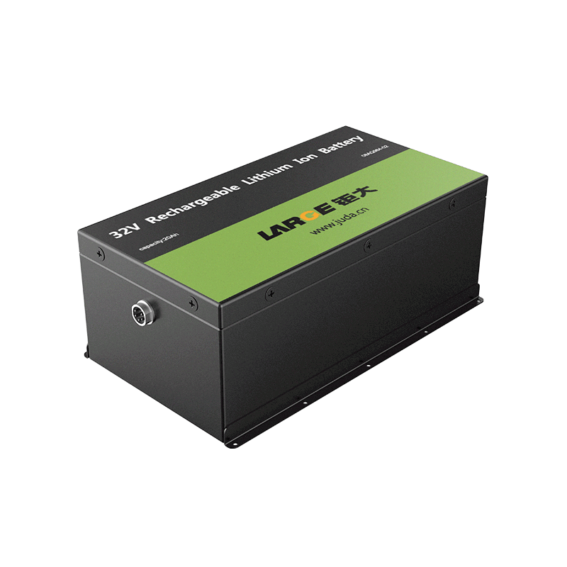
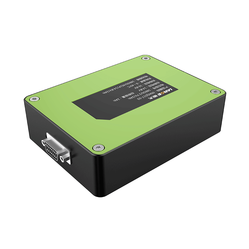
How to prevent the battery from being reversed?
Mar 29, 2019 Pageview:1276
As long as it is a battery-powered system, this problem has always existed: you mistakenly load the battery, reverse the positive and negative poles, and generate a reverse polarity event. The system has temporarily failed or is permanently damaged.
Custom batteries designed to fit the system they are equipped to help minimize the chances of incorrect insertion and reverse polarity, but are proven and reliable ready-to-use devices such as AAA, AA, C and D cells Batteries, and even CR123, CR2, and button lithium batteries are also prone to failure.
In the past, designers used mechanical structures to avoid electrical contact with the battery terminals (if the battery was not properly inserted). But mechanical solutions are far from perfect. They usually require special machining because the spring contacts require well-controlled mechanical component tolerances to ensure good contact when the battery is properly inserted, but not properly inserted and not in contact. These narrow tolerances can cause long-term stability problems because the springs and contacts that must be used may bend or fail. Even normal use, repeated normal insertions can cause contact fatigue and limit reliability over time.
But despite these limitations, mechanical solutions have always existed because they are the only practical solution that designers can use to prevent incorrect battery installation. Electrical solutions designed to prevent reverse polarity events caused by reversed phase batteries have been controversial.
Because of the voltage drop during normal operation, it is usually not the option to use a series diode. It is also not a good idea to use a diode grounding setting because a reverse polarity event can cause the battery to discharge dangerously for a long time and overheat the diode.
Discrete MOSFETs require complex structures and may not be optimized or specifically designed to prevent reverse polarity. Critical specifications for evaluating performance during reverse polarity events may be lost, and this may cause designers to have to derive estimates from performance characteristics on the data sheet and guess safe working time periods, which is worrying. Moreover, depending on how the MOSFETs are applied, they may require a controller or other costly function.
Multifunction ICs are sometimes equipped with circuits that prevent reverse polarity, which typically adds significant circuit complexity because they can operate in a positive biased environment and then operate in reverse polarity mode or not. Therefore, multi-function ICs bring huge performance and/or cost costs. Typical implementations have a relatively limited reverse bias function (-2V or -6V) due to cost-performance tradeoffs.
Dedicated reverse polarity protection device is an effective way to prevent erroneous insertion of the battery
Recently, however, the advent of dedicated reverse polarity protection devices has provided designers with more viable electrical options. Dedicated devices, such as those offered by Fairchild, represent one of the most cost-effective and performance-free methods to prevent reverse polarity and are an excellent choice for battery-powered systems.
This simple setup provides continuous and reliable protection. The design requires minimal PCB space, minimizes voltage loss, and responds quickly and efficiently under reverse bias conditions.
The overall cost is also good. Series Schottky diodes are generally less expensive than dedicated reverse polarity protection devices, but once the operating current begins to increase, the total cost based on the Schottky method begins to rise. For cost-effective trade-offs, dedicated reverse polarity protection devices are likely to be the most attractive electronic method.
People will continue to make mistakes on the battery, but the way designers can prevent minor accidents is likely to change. After considering the full range, dedicated reverse polarity protection devices may completely replace complex mechanical solutions over time.
Causes of reverse polarity formation and measures that can be taken
No one wants their system to malfunction, or even a more serious fire. However, this may happen if the reverse polarity is allowed to break.
The reverse polarity is the result of a steady state reverse bias or a negative transient. This is a dangerous electrical condition that is difficult to prevent once the system is shipped.
Reverse polarity risk is a real threat in a variety of common applications, including mobile electronics, battery powered systems, devices connected to automotive power supplies, DC powered toys, products with barrel jack connectors, or any heat that is subject to negative voltage Plug-in or inductive transient DC devices. Systems that support USB connectivity and/or USB charging are particularly susceptible.
Here are some of the most common reasons for reverse polarity:
Use aftermarket after market charger or power supply
The market for third-party chargers is growing, but not all chargers are designed with reverse polarity protection. In some cases, the charger has reverse electrical contacts or the polarity can be set by the user, which leaves room for errors.
Using USB's "hot plug" function
The ability to easily connect or disconnect mobile devices while the bus is in a powered state means that "hot swap" operations are increasing, as is the magnitude of hot plug transients. These inductive transients swing the bus to a reverse polarity condition. Although the time of these swings is often short, the magnitude is large. Voltage rail swings in excess of ±20V have been measured during "hot swap" operation. This transient can have an effect on the disconnected device and other devices on the voltage rail. This problem only gets worse when the charging current increases.
Use a battery that is not inserted correctly
A battery-powered system may malfunction because the battery is not properly inserted and its positive and negative terminals are reversed. This is especially true for AAA, AA, C, and D cell batteries, or devices with conventional form factors, such as CR123, CR2, or button lithium batteries. If the battery is properly inserted, the mechanical solution prevents electrical contact with the battery terminals, but these solutions require custom molding and can withstand contact fatigue over time.
Use of wall plugs in developing countries
There are also places in the world where the power infrastructure has fewer protection requirements, so the power supply can transmit large voltage transients down the line. Indoor wiring makes the situation worse. In the past, traditional incandescent lamps helped absorb and suppress transient energy on the power line, but new types of products like LEDs and CFLs did not have the same suppression characteristics. Energy-saving work by moving to LEDs and CFLs can create problems that have never been encountered.
Insert the device into the power supply of the car (or aircraft, train, etc.)
In many cases, power adapters in traffic power include reverse polarity protection, but there are exceptions, especially in low-cost alternatives. An unsuspecting user simply inserting the device into the lighter jack of the car can cause a reverse polarity event because he does not realize that the lighter jack can cause a device failure.
Since there are too many ways to trigger a reverse polarity event, the designer must do everything he can to prevent reverse polarity before the system leaves the factory to avoid damage.
Optimal protection method for reverse polarity in systems less than 100mA
Low-current systems—systems with operating currents below 100mA or 200mA—cover a wide range of applications, from safety systems and fire alarms to systems for building automation, public address and data networks.
This includes many different work environments, and designers cannot always predict where their systems will be used. Depending on the situation, the system may be exposed to poor electrical conditions such as steady state reverse bias or negative transients, which may cause reverse polarity events and damage the system.
The result may be as simple as an electrical fault, but if the situation is severe, it could result in a fire. Therefore, it is not uncommon for designers to add circuits to prevent the negative effects of reverse polarity.
There are several ways to do this, but for low current applications, the efficiency is usually less of a problem. As long as the system can withstand power consumption and the operating voltage drop is associated with each method, two simple methods of series PN or Schottky diode can be used to achieve the goal.
Series PN diode
If the design accepts a large series drop (±1V), or there may be a high voltage reverse transient (>200V), then using a series PN diode is a good choice. Figure 2 provides a design example. This is a simple, low-cost solution that provides fast blocking, resettable features and high breakdown voltage.
This diode consumes the least amount of power and therefore requires less heat sinks and is less expensive. As long as the device is not hot during normal operation or possible fault conditions, the system will work properly.
Even so, the solution is not suitable for every design. The cost advantage will soon disappear as the operating current increases. Moreover, at higher currents, the greater the power consumption, the more expensive the final required diode is, requiring a more thermally conductive package and heat sink structure.
In addition, in low voltage systems (≤ 5V), diode dropouts may require additional downstream boost circuits, which makes the methods that would otherwise be expected to be low cost actually expensive.
Therefore, be sure to keep these in mind before using the PN diode method.
Series Schottky diode
A similar but more widely used method is to use a series Schottky diode instead of a series PN diode. This voltage drop is a little lower (±0.6V) and the design consumes less power.
Lower voltage drops reduce the thermal management requirements associated with traditional PN diodes, which may result in smaller and lower cost packages.
Still, care needs to be taken because the pressure drop may still be too high for many applications. Moreover, although the operating range of Schottky diodes is wider than that of series PN diodes, the best application of this method is still using currents below 200mA and with higher voltages (>5 V).
In conclusion
Regardless of which method is used, the two main aspects of voltage drop and power consumption must be considered. Assuming both parameters are within acceptable limits, both methods can effectively protect low current systems from damage that can be caused by reverse polarity events at a low cost. If voltage drop or power dissipation is a problem, consider an active solution such as Fairchild's FR device.
The page contains the contents of the machine translation.
- Prev Article: Power battery development, high quality and high quality are the core
- Next Article: Fenggang Battery Factory Battery Fire Truth
Leave Message
Hottest Categories
-
Hottest Industry News
-
Latest Industry News


