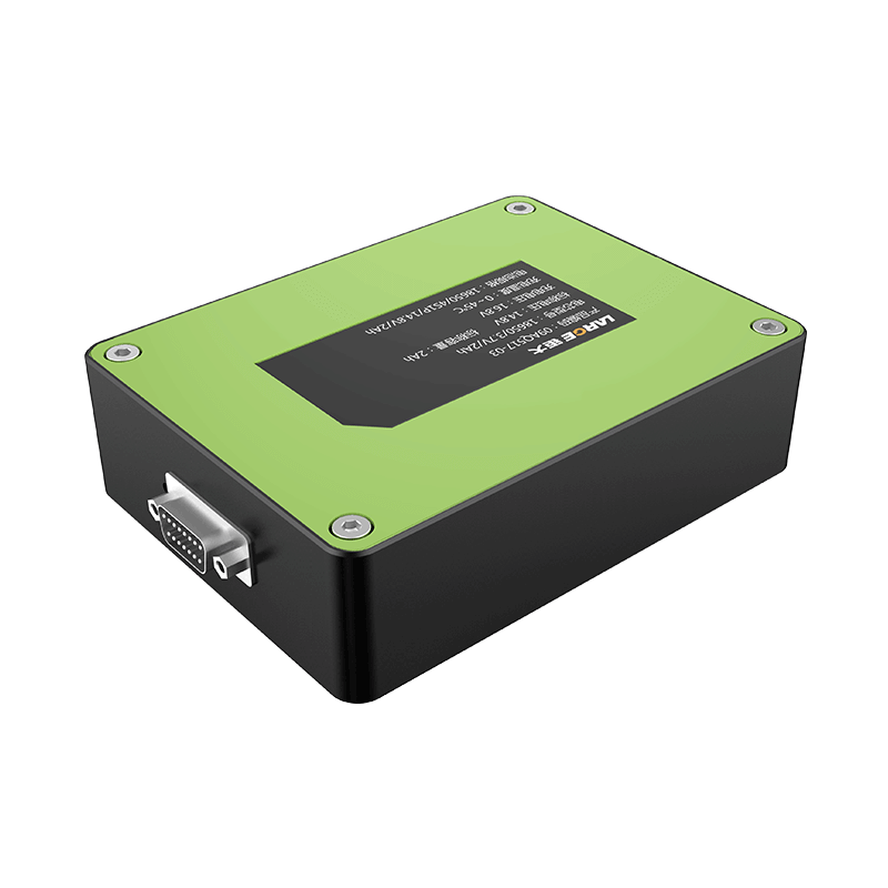
The working principle of the BMS lithium battery protection board
Jan 08, 2019 Pageview:1766
Power BMS lithium battery protection board
First, Composition of lithium battery
The lithium battery is mainly composed of two large blocks, the battery core and the protection board PCM (the power battery is generally called the battery management system BMS), the battery core is equivalent to the heart of the lithium battery, and the management system is equivalent to the brain of the lithium battery. The battery core is mainly composed of a positive electrode material, a negative electrode material, an electrolyte solution, a separator and an outer casing, and the protection plate is mainly composed of protection chip, chip (or management), MOS tubes, resistors, capacitors, and PCB board, etc.
Second, the advantages and disadvantages of lithium battery
Lithium batteries have many advantages, high voltage platform, high energy density (light weight, small size), long service life and environmental protection.
The disadvantage of the lithium battery is that the price is relatively high, the temperature range is relatively narrow, and there is a certain safety hazard (requires a protection system).
Third, the classification of the lithium battery
Lithium battery can be divided into two broad categories: one-time don't charge the battery and the second rechargeable battery (also known as the battery).
Non-rechargeable batteries such as: lithium manganese dioxide batteries, lithium-sulfuramide batteries.
Fourth, all kinds of power battery
Power battery is more to consider the application of, mainly used in electric, electric cars, electric bicycles, electric tools, etc.
Power battery from the batteries and the particularity of its certain:
1. Battery series parallel
2. The battery capacity is larger
3. The battery discharge ratio is bigger (hybrid and electric tools)
4. High security requirements of the battery
5. Wide working temperature of the battery
6. The battery service life is long, generally requires 5 ~ 10 years
Fifth, the BMS function is introduced and analyzed
1. The battery protection, and PCM, overcharge, discharge, temperature, flow, and short circuit protection. Like ordinary lithium-manganese batteries and ternary lithium batteries, once any battery voltage exceeds 4.2V or any battery voltage is lower than 3.0V, the system will automatically cut off the charging or discharging circuit. If the battery temperature exceeds the working temperature of battery or current is greater than the discharge current of the battery, the system will automatically cut off the current path, battery, and system security.
2. The energy balance, the whole battery pack, because a lot of batteries in series, work after a certain period of time, due to the inconsistency of the cell itself, partly due to the inconsistency of working temperature, the influence of the last will show a big difference, for the life of the battery and the use of the system has a huge impact, energy balance is to bridge the differences between individual batteries to do some active or passive charge or discharge of management, to ensure the consistency of the battery, prolong the service life of battery.
Industry generally there are two kind of way, passive equilibrium and active equilibrium of passive equalization is mainly the electricity power consumption by resistance to achieve more balanced, active balance mainly is the amount of battery power through the capacitor, inductor or transformer to achieve balanced less battery.
Due to the active balancing system is relatively complex, cost is relatively high, the mainstream still passive equalization.
3. SOC calculation, battery power calculation is a very important part of BMS, many systems need to know the remaining power more accurately. Due to the development of technology, many methods of SOC calculation accumulate, the accuracy requirement is not high, and the remaining power can be judged according to the battery voltage. The accurate method is mainly the current integration method (also called Ah method), Q=∫idt, and Internal resistance method, neural network method, Kalman filter method, etc. The mainstream in the industry is still the current scoring method.
4. Communication, different system is different to the requirement of communication interface, the mainstream of communication interface with SPI, I2C, CAN and RS485, etc. The vehicle and energy storage system is mainly the CAN and RS485.
BMS system because the competition is not enough, and the complexity of the system, the system vendor is relatively small, the chip manufacturers are mainly Europe and the United States, several companies have a few large companies in the research and development. Many opportunities in the future.(to tell everyone about protection plate appear bad below analysis)
Sixth, protection board bad analysis
1, no display, low output voltage, with no load:
Such bad first ruled out bad batteries (batteries was no voltage or low voltage), if the batteries is bad should test protection board since the power consumption, since the power consumption is too large to see whether the protection plate leads to low voltage batteries. If the batteries voltage is normal, is because of the whole circuit protection board impassability components (virtual welding, welding, FUSE, PCB circuit inside the impassability, via impassability, MOS, IC damage, etc.).A concrete analysis
Steps are as follows:
(1), Use the black meter of the multimeter to connect the negative pole of the battery. The red test lead is connected to the FUSE and R1 resistors at both ends. The Vdd, Dout, Cout end of the IC and the P+ end (assuming the battery voltage is 3.8V) are analyzed step by step. These tests are performed. The point should be 3.8V. If not, there is a problem with this segment of the circuit.
1. Both ends of the FUSE voltage change: testing whether the FUSE conduction, if the general principles of the guide is the internal PCB circuit impassability; If not the general principles of the guide there is something wrong with the FUSE (incoming bad, over-current damage (MOS) or IC control failure, material has a problem (in the MOS or IC action before the FUSE is burnt), then use wire short FUSE, continue to back analysis.
2. There is a change in the voltage across the R1 resistor: Test the resistance value of R1. If the resistance value is abnormal, it may be a virtual solder, and the resistor itself is broken. If there is no abnormality in the resistance value, there may be a problem with the internal resistance of the IC.
3. The voltage of the IC test has changed: the Vdd end connected to R1 resistor. Dout, Cout is unusual, is due to the IC virtual welding or damaged.
4. If the voltage is no change: testing - to the abnormal voltage between P + B, is due to protect look extremely via impassability.
(2), multimeter red pens and batteries positive, after activated MOS tube, black pens and, in turn, meet the MOS tube, 2, 3 feet 6 or 7 feet, P - end.
1. MOS tube 2 and 3 feet, 6, 7 feet voltage change, MOS tube abnormalities.
2. No change if MOS tube voltage, voltage of the P - exceptions, is due to the cathode protection plate via impassability.
Seventh, Short circuit without protection
Problems: 1. there is a problem with the VM end resistor: the IC2 pin can be connected with a multimeter and a pen to connect the MOS tube pin connected to the VM end resistor to confirm the resistance value. Look at the resistance and the IC, MOS pins have no solder joints.
2. IC, MOS anomalies: due to the discharge protection and over current, short circuit protection Shared a MOS tube, if the short circuit is abnormal, given the problems in the MOS is this plate should be done no protection function.
3. Under the normal condition for more than bad, may also appear abnormal IC with poor caused by short circuit of MOS configuration. Such as the early stage of the BK - 901, the model of "312 d" within the IC delay time is too long, cause before the IC to make corresponding action control MOS or other components have been damaged. Note: one to determine whether the IC or MOS an exception occurs the most simple, direct method is to have a suspicious components for replacement.
Eighth, short circuit protection of self recovery
1. The design USES no IC self-restore function itself, such as G2J, G2Z, etc.
2. The instrument set short recovery time too short, or short circuit test will load, short circuit such as multimeter voltage shift after the pens and sub will not pens and removed from the test end (multimeter is equivalent to a few megabytes of load).
3. P +, P - leakage, such as welding plate between the impurities of rosin, cement with impurities or P +, P - capacitance is punctured, the breakdown between ICVdd to Vss. (only a few K to a few hundred K value).
4. If the above are no problem, may be the breakdown of IC, can test the IC value between each pin.
Ninth, the internal resistance is large
1. Since the internal resistance of MOS is relatively stable and there is a large internal resistance, the first thing to suspect is that the internal resistance of FUSE or PTC is relatively easy to change.
2. If the FUSE or PTC resistance is normal, depending on the protection board structure detection P +, P - between welding plate and components surface via resistance, probably via appear slightly off phenomenon, resistance is bigger.
3. If there is no problem with the above, it is necessary to doubt whether the MOS is abnormal: first, determine whether there is any problem with the welding; secondly, the thickness of the board (whether it is easy to bend), because the bending may cause the pin to be welded abnormally; then the MOS tube Place it under the microscope to see if it breaks. Finally, use a multimeter to test the resistance of the MOS pin to see if it is broken down.
Tenth, ID anomaly
1. The ID resistor itself is abnormal due to virtual welding, breaking or the resistance material is not closed: the two ends of the resistor can be re-welded. If the ID is normal after re-welding, the resistance is weak soldering. If it is broken, the resistor will be cracked after re-welding.
2. ID via is not conductive: you can test both ends of the holes with a multimeter.
3. There is a problem with the internal circuit: the solder resist can be scraped off to see if the internal circuit is disconnected or has short circuit.
The page contains the contents of the machine translation.
- Prev Article: Can bulge battery also be used?
- Next Article: How do you recycle lithium batteries?
Leave Message
Hottest Categories
-
Hottest Industry News
-
Latest Industry News


