Linear charging solution for lithium ion batteries
Oct 17, 2019 Pageview:1349
With the development of modern electronic technology, electronic equipment is increasingly tend to be more portable, more functional, and thus the power supply to them battery light weight and efficient requirements are put forward. Lithium ion batteries with its high energy density, charge and discharge performance is excellent, non-polluting characteristics gradually replace the traditional nickel cadmium, nickel metal hydride batteries, lead-acid batteries are widely used in modern portable electronic products.
Relative to other types of batteries, lithium ion battery in performance at the same time, it puts forward higher requirements on the charger, these requirements are mainly embodied in the charging process and the control of the lithium battery protection, embodied in the larger charge voltage, phase current, high precision of charging mode and perfect protection circuit, etc.
In this paper, we discuss using large current lithium ion battery chip SE9018 linear charging scheme design of lithium ion battery.
The chip is introduced
SE9018 is a constant current/constant voltage mode of lithium ion battery linear charge chip, using internal PMOSFET architecture, and integrated with protection charging way, don't need external isolation diodes.
Chip preset charge voltage of 4.2 V, the accuracy of plus or minus 1.5%, charging current can be set up through the external resistors, maximum continuous charging current can be up to 1 a.When the chip due to the large power and high ambient temperature or poor PCB thermal performance causes junction temperature higher than 140 ℃, the internal heat will automatically reduce the charging current feedback circuit, the chip temperature control in the security area.To make the chip to maintain efficient work status, measures should be taken to try to reduce the working power and chip temperature, such as the input series small resistance (to reduce the input voltage), increase the cooling area of copper foil for PCB, chip heat sink and PCB good contact with copper foil, etc.
Figure 1 se9018 foot bitmap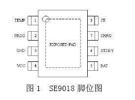
Figure 2 se9018 schematic diagram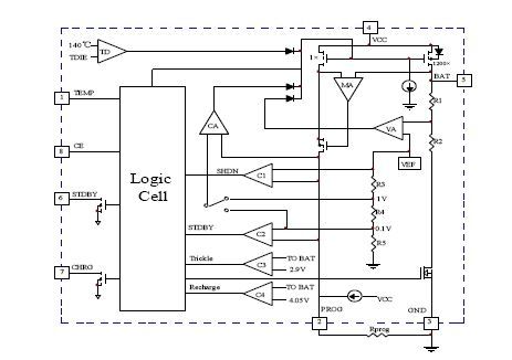
SE9018 internal integration battery temperature monitoring circuit, beyond the normal range when the battery temperature (too high or too low), chip automatically stop charging process, prevent cell damage because of the temperature too high or too low.
Voltage of the battery temperature monitoring is by judging TEMP (VTEMP), VTEMP by a including battery internal resistance, NTC thermistor network provide partial pressure.
When VTEMP between * VCC VCC and 80% 45%, chip judgment battery temperature in the normal range;When VTEMP < 45% (VCC or VTEMP > 80% (VCC, chip judgment battery temperature too high or too low;When the TEMP end grounding, battery temperature monitoring function is disabled.
SE9018 contains two drain CHRG and STDBY open status indicates output end, when the circuit is in a state of charge, CHRG end low level, STDBY end as the high impedance state;When the battery is full, the CHRG end into a high impedance state, STDBY end low level.When the battery temperature monitoring function normal use, if the chip is not connect the battery or the battery temperature is beyond the normal range, CHRG end and STDBY end are the high impedance state;When the battery temperature monitoring function is disabled, if not connected battery chip, for low level STDBY end, CHRG output pulse signals.
Other features include manual stop SE9018, undervoltage lockout, automatic recharge, etc.
Typical SE9018 based lithium-ion battery charging circuit is shown in figure 3.CE side for high electricity at ordinary times, SE9018 work properly.
Smart large current lithium ion battery linear charging scheme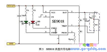
Figure 3 se9018 typical application circuit
1. The charging current Settings
Constant current charging in the process of charging current Ibat by PORG end and GND end resistance between Rprog setting, Ibat relations with Rprog resistance is:
Formula 1
For example, if you want a 1 a constant charging current, according to the formula 1 available Rprog Ω = 1200.
2. The battery temperature monitoring circuit setting
Battery temperature monitoring circuit set is mainly to set of R1 and R2, assuming that the NTC thermistor in the resistance of the minimum operating temperature for RTL, in the resistance of the highest working temperature for the RTH (RTL and RTH can check the data related to the battery manual or) is obtained by experiment, R1, R2 of resistance are:
Formula 2
The formula 3
In practice, if only need high temperature protection, do not need low temperature protection, R2 can be removed.At this point, the R1 value for:
The formula of 4
3. Manual setting downtime
In the process of charging, may at any time through the CE side for low level or to remove the Rprog (PROG floating) puts SE9018 stop condition, the battery leakage current dropped to below 2 ua, input current dropped to below 70 ua.
4. Under voltage blocking state
If the input voltage VCC below under-voltage lockout threshold or VCC and battery voltage Vbat difference is less than 120 mv, SE9018 in undervoltage lockout condition.
When the chips are in a state of downtime or undervoltage atresia, CHRG end with STDBY end are the high impedance state.
5. Normal charging cycle
When SE9018 all the input and the battery is in normal state, the charging circuit into the normal charge cycle, the cycle includes four basic working modes: a trickle charging, constant current, constant voltage charging end of charging, charging and recharging.
Vbat is lower than 2.9 V battery voltage, charging circuit into a trickle charging mode, the charging current for one over ten of the constant current charging current (if constant current charging current is set to 1 a, the trickle charging current of 100 ma), a trickle charging status will remain to the battery voltage Vbat is 2.9 V.A trickle charge mode is mainly to avoid large current shock when the battery voltage is too low to battery internal structure.
But less than the preset charge the battery voltage is higher than 2.9 V voltage of 4.2 V, the charging circuit is in constant current charging mode, as described above, be determined by the Rprog charging current.
When the battery voltage is 4.2 V, charging circuit into constant-voltage charging mode, the voltage of the BAT at 4.2 V, charging current decreases.The process of the main effect is to reduce the influence of battery internal resistance to charge voltage, make the battery more fully.
The page contains the contents of the machine translation.
Leave Message
Hottest Categories
-
Hottest Industry News
-
Latest Industry News


